Electrical Measuring Instruments
The main electrical measuring instruments: Ammeter, Voltmeter, Ohmmeter, Wattmeter, Multimeter. Measuring current can also be used to estimate your electricity consumption, but also to check the condition of your installation and identify energy losses.
Ammeter or Ampermeter
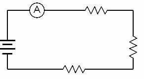
The ammeter is the device used to measure the intensity of the current flowing in a portion of an electrical circuit.
An ammeter is always connected in series with the device whose current intensity is to be measured.
In order not to break the device, it is recommended to always start taking a reading using the largest scale (the scale that can give the greatest value of electrical current). We can scale down afterwards to take the most accurate reading of our electric current.
The scale of the device obviously takes into account the deflection of the electrons. The device is calibrated accordingly. There can be several scales on an ammeter.
Internal workings of an ammeter
The ammeter is a device derived from the galvanometer. Its operation is relatively simple. Electric current enters the device and, since the shunt resistor is a component that offers a very low resistance, the majority of the electric current will pass through the shunt resistor. A small electric current will flow through the voice coil (the solenoid). This electric current will generate a magnetic field and the voice coil will be deflected, since the voice coil is surrounded by a permanent magnet. The needle is attached to the voice coil. The voice coil therefore carries the needle with it.
Read also: Electrical Fuse | Role and Types in Electricity
The greater the electric current, the more electrons will flow through the voice coil. The magnetic field will then be even greater, the coil will be much more deflected and the needle will indicate a greater current measurement.
Excercises
An ammeter should have _____ resistance?
A) Infinite
B) Very large
C) Very low
D) None of the above
Answer: C) Very low
Can you explain why an ammeter should be of very low resistance?
Answer:
Ammeter, which is connected in series with the circuit carrying the current under measurement, must be over very low resistance so that the voltage drop across the ammeter and power absorbed from the circuit are as low as possible.
An ammeter is connected in _____ with the circuit element whose current we wish to measure?
A) Series
B) Parallel
C) Series or parallel
D) None of the above
Answer: A) Series
Voltmeter
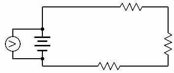
The voltmeter is the device used to measure the voltage in an electrical circuit.
A voltmeter is always connected in parallel with the device whose voltage is to be measured.
There can be several scales on a voltmeter. In order not to break the device, it is recommended to always start taking a reading using the largest scale (the scale that can give the greatest voltage value). You can scale down later to take the most accurate voltage reading.
Internal workings of a voltmeter
The voltmeter is a device derived from the galvanometer. Since the voltmeter is not a device that must measure the amount of electric current, the access of current to the device is limited by using high resistance coils. Thus, the voltmeter will only steal a very small portion of the current flowing through the circuit. The weak electrical current that then enters the device travels through the voice coil (the solenoid). This electric current will generate a magnetic field and the voice coil will be deflected since the voice coil is surrounded by a permanent magnet. Like the ammeter, the needle is attached to the moving coil. The voice coil therefore carries the needle with it.
The greater the electric current, the more electrons will flow through the voice coil. The magnetic field will then be even greater, the coil will be much more deflected and the needle will indicate a higher voltage. The device is calibrated accordingly.
Voltmeter
Like the multimeter, the ammeter or the ohmmeter, the voltmeter is an electrical measuring device. But the particular role of the voltmeter is to differentiate the electric potential between two poles. More concretely, the voltmeter is used to determine the voltage (V) between two points.
Indeed, in a circuit, the batteries are generally 4.5 V, divided into 4.5 V on the phase (point A) and 0 on the neutral (point B). This difference of 4.5 V can apply in various cases within the electrical circuit of a house, and it is only noticed in the light of the voltmeter, an electrical tester available in several types. In fact, on the market of current measuring devices, you can acquire two types of voltmeter: the analog voltmeter and the digital voltmeter.
With the first, the analog voltmeter, the measurement of the data of the electrical circuit is done by means of a needle placed on a scale of magnitudes. On the other hand, with the second, the digital voltmeter, or digital voltmeter, you will be entitled to a display on an LCD screen.
Through this page, you will discover advice and everything you need to know about the voltmeter. We help you find out about the use of this voltage tester, the criteria for choosing it and we offer you a complete comparison of the voltmeter models available for sale.
WHAT IS THE FUNCTION OF THE VOLTMETER?
Voltmeter is one of the electrical measuring instruments.
The voltmeter is primarily a device for measuring the voltage of the current in an electrical circuit. To know what a voltmeter is used for, we can look at its use in three different situations.
In the first case, this electrical tester will allow you to unmask a possible current leak in your electrical installation. Indeed, the voltage of it is supposed to be 220 to 230 V. The check is done by connecting the voltmeter to a live device. A probe is then placed on the phase and the neutral. When the result obtained by the voltmeter is less than 220 V, you can conclude that there is a current leak.
In the second case, the voltmeter is used to know if a circuit is powered by an electrical frequency. This analysis is particularly important before any intervention on a device running on electrical energy. In fact, checking the current voltage with the voltmeter saves you a probable electrocution.
Finally, the voltmeter is also used to determine the role of each of the components of an electrical circuit. The electrical tester is mainly used during renovation work, to determine the phase and the neutral.
EXISTING TYPES OF VOLTMETER
The voltmeter offer is based on two different types of measuring tool. We distinguish on the one hand the analog voltmeter and on the other hand the digital or digital voltmeter. The first, the analog voltmeter, is a classic model that has been used for years. This is a variation of the voltmeter consisting of a case and a needle. To use it, it must be calibrated, then place the probes of the device on a circuit. From then on, the device takes care of calculating the potential difference between the two points to be evaluated. The data is indicated by the needle. Very common and available at various prices, the analog voltmeter has as many disadvantages as advantages.
In terms of benefits, the device is known to be convenient, accurate and easily accessible. Indeed, the analog voltmeter makes it possible to identify reliable data on the voltage of the electric current, whether it is an alternating current or a direct current.
In addition, this type of voltmeter has something to seduce by its autonomy, since it works on batteries. This characteristic makes it a fairly practical voltmeter, as we pointed out above, because it does not require the use of external batteries and makes it possible to avoid breakdowns during its use.
However, it should be noted that the analog voltmeter is not free from disadvantages. Indeed, the main defect of analog voltmeters is their poor readability. It must be said that with its dial equipped with a needle, reading the data recorded by an analog voltmeter can be complex, especially when it comes to the first uses of the device. Using the tester can be more difficult if you do not master the reading method. And that’s not counting the transcription errors that the voltmeter cannot avoid.
Moreover, it is a type of device with limited functionality. The absence of a backlit screen or a lamp placed at the back of the device is a good illustration of the limits of the analog voltmeter.
The second type of voltmeter, the digital voltmeter, has the same mode of operation as the analog voltmeter. However, it differs in a few aspects. The main indicator of the difference between the analog voltmeter and the digital voltmeter is the digital display of it. Indeed, the digital voltmeter is generally equipped with a backlit screen that allows you to read the results clearly.
With this feature, the digital voltmeter appears as a modernized model of the analog type. Logically, its performance is much better than that of the analog voltmeter.
In fact, with a digital voltmeter, the illuminated display allows great and perfect readability. Similarly, the results collected are precise and reliable. This type of voltmeter has all the characteristics to serve both in the light and in the shade.
Moreover, its use is not complex, unlike that of the analog voltmeter, which requires a mastery of the operation of the measuring device. To select an option on your digital voltmeter, you will only have to calibrate it using a wheel with which the case is equipped. This feature reinforces the security guaranteed by the tester.
If you find the calibration complicated, you can opt for an automatic digital voltmeter model. This category of voltmeter offers a “HOLD” option, which allows instantaneous recording of data.
Excercises
Explain what is voltmeter multiplier?
Answer: voltmeter multiplier is a high non-inductive resistance connected in series with the voltmeter coil and is used for increasing the range of a voltmeter
The internal resistance of a voltmeter must be very high so that
A) Range is high
B) Minimum current passes through the meter
C) Loading effect is maximum
D) Accuracy is high
Answer: B. Minimum current passes through the meter
If we need to measure an unknown voltage with a manual-range voltmeter. This particular voltmeter has several different voltage measurement ranges to choose from: 5, 10, 25, 50, 100, 250, 500 VOLTS. Can you answer and explain what range would be best to begin with, when first measuring this unknown voltage with the meter?
Answer: begin by setting the voltmeter to its highest range: 500 volts. Then, see if the movement needle registers anything with the meter leads connected to the circuit. Decide to change the meter’s range based on this first indication.
If a voltmeter with resistance in Rv = 10 kV which has a maximum measuring limit of 100 V. If this voltmeter will be used to measure potential difference up to V = 1000 V, then calculate the amount of series resistance that must be fitted to the voltmeter!
Answer: the ratio between the potential difference to be measured and the maximum measuring limit is:
n= [(1000 V / 100V] = 10
By using the equation using an ammeter to measure electric current, we get the series resistance Rs:
Rs = (n -1) Rg
= (10 – 1) 10 kV
= 90 kV
Ohmmeter
If you get into any electrical work, you may need an ohmmeter in many situations. This device allows you to measure the resistance of an electronic or electrical circuit. It will come in handy very often.
An ohmmeter is a measuring instrument that measures the electrical resistance of an electrical component or circuit. The unit of measurement is the ohm, denoted Ω.
What is an ohmmeter?
The ohmmeter is a device that looks a bit like a multimeter and allows you to measure the resistance of a load. It is widely used in electronics or in the context of electrical work. It measures electrical current in ohms and allows you to spot electrical problems in the home. The ohm is the measure of resistance in an electrical circuit.
Formula
R = V/I.
If a problem involves the factors affecting the resistance of a conductor, R can be calculated using R = ρL/A. If it involves resistance and temperature, R can be found using R = R0 (1+αΔT). The SI unit of resistance is the ohm (Ω)
What is an ohmmeter used for?
In most uses, the ohmmeter is used to test an appliance motor, but also a fuse or even an iron. The goal is to know if they are grilled or not grilled.
Open: means that the circuit is open: in this case the ohmmeter displays a 1 in the display panel. The value exceeds the range, it means that the load is good to replace, a fuse for example. An open circuit has a large resistance.
Not burnt out: the circuit is then closed and the ohmmeter then displays a value close to zero. This means that the fuse or motor is still good.
It offers the possibility of checking that a device has no electrical leakage to ground or that there is no short circuit. The current continuity test is performed with a beep indicating its passage.
How does the ohmmeter work?
It works simply by sending a small current through a circuit using two metal keys, which allows it to measure its resistance. It needs to be configured to give you a set measurement, and then you can do the actual measurement.
You start by disconnecting the load from the circuit to be measured and then you place the ohmmeter across its terminals. The device, through its internal battery, circulates a very low current in the load and measures the voltage, which makes it possible to quantify its resistance.
Operating principle
Two methods can be used to measure the value of a resistor:
Current measurement with a voltage generator
Measurement of a voltage with a current generator.
How do you use your ohmmeter?
The device must be properly powered. It has a small battery or batteries that may or may not be already installed. The power supply is sometimes provided and you will need to install it. Some devices can be powered by a small transformer.
There are different ohmmeters:
1. Analog or mechanical ohmmeters: they are quite simple in design, so they are inexpensive to buy. They can measure low resistances (0 to 10 Ω), but also high resistances (0 to 10,000 Ω). They have the same measurement ranges, but the advantage is that it has an automatic function for the choice of the range. Just plug it into the circuit and then it adjusts itself.
2. Digital ohmmeters: these new generation devices are intuitive. They display the resistance value of the measured body directly on the LCD display screen. This type of ohmmeter has many features:
- Body resistance measurement after DC/AC circuit current analysis.
- Evaluation of the conductivity of a component by measuring the voltage.
- It has the possibility to switch between the different ranges offered.
- Precise indications on the selected range.
- Measurement according to several types of resolution.
3. Micro-ohmmeters: they are designed to detect resistances of only a few tens of Ohms. The level of precision can even approach microohms. These are mostly digital devices. They integrate:
- Seven measurement ranges
- Three Selection Modes
A digital screen - A rechargeable battery
- Voltage presence detection
- A maximum continuous test current of approximately 10 amps
Excercises
If an ohmmeter connected to across a closed switch will display around:
A) 0 ohms
B) 1k ohms
C) 100k ohms
D) 1000k ohms
Answer: 1. 0 ohms
If an ohmmeter connected across an open switch will display:
A) 0 ohms
B) 100 ohms
C) 50 kohms
D) 0L
Correct answer: 4. 0L
Because 0L indicates very high (out of range of ohmmeter) or open loop. An open-loop has infinite resistance.
If a series ohmmeter circuit uses a 3 V battery and a 1 mA meter movement. What is the half scale resistance for this movement?
A) 3 kO
B) kO
C) kO
D) 6 kO
Answer: A
Wattmeter
It is an instrument that measures the electrical power drawn at any time by an electrical or electronic device, or a lamp. The power, which is given in watts (W), represents the electrical energy consumed each second.
Some wattmeter models can also measure the total electrical energy consumed over a certain period of time, for example over 24 hours: this energy is given in kilowatt hours (kWh).
Please note: not all wattmeters are capable of detecting the low powers of the order of 1 to 5 watts that many electrical and electronic devices – as well as certain lamps fitted with a transformer or dimmer – draw even when ‘they are apparently extinct (hidden consumption). Most power meters have a threshold below which they indicate “0 watts”, even if the appliance or lamp is drawing a few watts. Fortunately, there is a trick (see below) that allows them to be used to measure these low powers.

Energy cost meter with Wattmeter. Popey900 12:29, 23. Okt. 2007 (CEST), Copyrighted free use, via Wikimedia Commons
Use limited power meter
by its measurement threshold
Inexpensive power meter models usually fail to measure power below 5 watts. Below this threshold, they indicate “0”.
They can nevertheless be used to measure the low powers that many devices draw when they are switched off. Just take an incandescent bulb (the traditional old light bulb) and place it in parallel with the device to be measured. You can use a multiple socket or a multi-socket strip (without switch). The bulb, once lit, will pass the threshold of the wattmeter (see the procedure on the left).
Translate the measurement threshold into watts
The power meter’s measurement threshold is usually given somewhere in the user manual in amperes (A) or milli-amperes (mA). It is sometimes mentioned under “starting current”. This information can be converted into watts, using the following formula:
threshold (ampere) x voltage (volts) = power (watts)
For a wattmeter whose threshold is given at 10mA:
0.01 amp x 230 volts = 2.3 watts
LCR meter
An LCR meter (inductance (l), capacitance (C) and resistance (R)) is an instrument used to measure the inductance, capacitance and resistance of a component, sensor or other device whose operation depends on capacitance, inductance or resistance.
Digital LCRs measure the current (I) through a device under test (DUT), the voltage (V) across the DUT, and the phase angle between the measured V and I. From these three measurements, all impedance parameters can then be calculated. A typical LCR meter has a four-terminal Kelvin connection to connect to the DUT under test. The Kelvin connection minimizes errors due to wiring and connection to the DUT.
Types of LCR Meters
There are a variety of LCR meters ranging from handheld to benchtop.
The Handheld Digital Multimeter with Capacitance Measurement is designed primarily as a digital multimeter, but uses a direct current technique to measure capacitance. The capacitance measurement is based on the measurement of the DUT’s RC time constant and computing capability. Meters in this class typically have an accuracy of +/- 1%.
Portable LCRs have the advantage of being lightweight, portable and battery operated.
Benchtop LCR meters typically offer more features than handheld devices, such as programmable frequencies, better measurement accuracy to 0.01%, computer control, and data collection for automated applications. Advanced features such as DC bias voltage and DC bias current and slew capability are common. LCRs in this category are used for AC calibration of inductance, capacitance, and resistance standards, dielectric constant measurements with various dielectric cells, and production testing of components and sensors.

LCR meter. ZngZng, CC BY-SA 3.0, via Wikimedia Commons
Test frequency
Electrical components should be tested at the frequency that the final product/application will be used. An instrument with a wide frequency range and multiple programmable frequencies provides this platform. Common measurement frequencies are 50/60 Hz, 120 Hz, 1 kHz, 100 kHz and 1 MHz. LCRs with programmable frequencies offer the most flexibility, tailoring the measurement frequency to the frequency at which the DUT will actually be used or in R&D applications where frequency characterization is useful to determine the useful frequency range . Most LCRs today use an AC test signal over a frequency range of 10 Hz to 2 MHz.
Test voltage
The AC output voltage of most LCRs can be programmed to select the signal level applied to the DUT. Generally, the programmed level is obtained under open circuit conditions. A source resistor (Rs, internal to the meter) is effectively connected in series with the AC output and there is a voltage drop across this resistor. When a test device is connected, the voltage applied to the device depends on the value of the source resistance (Rs) and the impedance value of the device.
Accuracy / Speed
Classic compromise. The more accurate your measurement, the more time you take and vice versa, the faster your measurement, the less accurate your measurements. This is why most LCR meters have three measurement speeds: slow, medium, and fast. Depending on the device under test, you have the choice between accuracy and speed. Average mode and median mode can also help improve measurement accuracy, but increase measurement time. It is also important to review the accuracy formulas in the manuals, as the actual measurement accuracy varies with the frequency, voltage, and impedance of the DUT.
Measurement parameters
The primary parameters L, C and R are not the only electrical criteria to characterize a passive component and there is more information in the secondary parameters than just D and Q. Measurements of conductance (G), susceptance (B), angle phase (q) and ESR can more fully define an electrical component, sensor or material.
Multimeter
A multimeter is a device that combines a voltmeter, an ammeter and an ohmmeter in a single and unique housing. This is one of the electrical measuring instruments.
A multimeter therefore has the advantage of allowing the measurement of current intensity, voltage and electrical resistance without having to connect several devices.
The ohmmeter is a device that is used to measure only the electrical resistance of a resistor or an electrical circuit. There are two main methods of operation. The device can impose a current intensity through the unknown resistance using a current generator and thus measure the voltage obtained. In the second method, the device can impose a voltage across the terminals of the resistor or the circuit using a voltage generator and thus measure the intensity of the current flowing there. Regardless of the method, the device will apply Ohm’s Law to determine the resistance value.
Excercises
If a multimeter has a sensitivity of 1000 O per volt and reads 50 V full scale, its internal resistance is?
A) 20 kO
B) 50 kO
C) 10 kO
D) None of the above
Answer: B) 50 kO
What is the role or purpose of a rectifier in a multimeter?
A) bias purpose
B) rectification
C) inversion
D) thermal stability
Answer: B
Clarification: When the multimeter is used for the measurement of A.C. voltages, rectifier section is used. It mainly performs the conversion of the input A.C. voltage into D.C. for the measurement of A.C. voltage.
Basic circuit of multimeter consists______
A) of a.c. amplifier
B) operational amplifier
C) of d.c. amplifier
D) power amplifier
Answer: c
Clarification: A.C. as well as D.C. voltage, current and resistance can be measured by making use of an electronic multimeter. Basic circuit of a multimeter is made up of d.c. amplifier circuit in the form of a balanced bridge.
What can limit the input signal magnitude?
A) button
B) resistance
C) voltage
D) attenuator
Answer: D
Clarification: A range switch is provided in an electronic multimeter in order to limit the input signal in terms of magnitudes. You can adjust the input attenuator and limit the input signal in terms of magnitude.
Is it true or false? A Multimeter can be used only for low resistance measurement.
A) False
B) True
Answer: A
Clarification: A multimeter is used for the measurement of A.C. as well as D.C. voltage, current and resistance. If you manipulating the scale with a multiplication factor of 100 and 10, 000 we can make use of a multimeter for measuring high resistances.
Is it true or false? An electronic multimeter consists of a rectifier.
A) False
B) True
Answer: B
Clarification: An electronic multimeter is used for the measurement of A.C. as well as D.C. voltage, current and resistance. It consists of a rectifier section that is used to convert the a.c. input signal to d.c. voltages.
Multimeter can be used as an ammeter by______
A) connecting shunts
B) making use of a transformer
C) connecting series resistances
D) making use of a transducer
Answer: A
Clarification: Electronic multimeter can be used as an ammeter by making use of shunt resistances across the meter. This is achieved by range selecting switch.
Multimeter can be used for D.C. voltage measurement by______
A) using a switch
B) connecting shunt resistances
C) connecting star delta resistances
D) connecting series resistances
Answer: D
Clarification: You can obtain a wide range of D.C. voltage from a multimeter by connecting various series resistances in the circuit through a range selection switch. By adjusting the value of the resistance we get the required D.C. voltage.
Below is the list of measuring instruments used in electrical and electronic work
| Name | Purpose |
|---|---|
| Ammeter (Ampermeter) | Measures current |
| Capacitance meter | Measures the capacitance component |
| Current clamp | Measures current without physical connection |
| Curve tracer | Applies swept signals to a device and allows display of the response |
| Cos Phi Meter | Measures the power factor |
| Distortionmeter | Measures the distortion added to a circuit |
| Electricity meter | Measures the amount of energy dissipated |
| ESR meter | Measures the equivalent series resistance of capacitors |
| Frequency counter | Measures the frequency of the current |
| Leakage tester | Measures leakage across the plates of a capacitor |
| LCR meter | Measures the inductance, capacitance and resistance of a component |
| Megger tester | Measures Resistance of an Winding of Motor or Generator And Measures Earthing’s Resistance |
| Microwave power meter | Measures power at microwave frequencies |
| Multimeter | General purpose instrument measures voltage, current and resistance (and sometimes other quantities as well) |
| Network analyzer | Measures network parameters |
| Ohmmeter | Measures the resistance of a component |
| Oscilloscope | Displays waveform of a signal, allows measurement of frequency, timing, peak excursion, offset, … |
| Psophometer | Measures AF signal level and noise |
| Q meter | Measures Q factor of the RF circuits |
| Tachometer | Measures speed of motors |
| Signal analyzer | Measures both the amplitude and the modulation of a RF signal |
| Signal generator | Generates signals for testing purposes |
| Spectrum analyser | Displays frequency spectrum |
| Sweep generator | Creates constant-amplitude variable frequency sine waves to test frequency response |
| Transistor tester | Tests transistors |
| Tube tester | Tests vacuum tubes (triode, tetrode etc.) |
| Wattmeter | Measures power in a circuit |
| Vectorscope | Displays the phase of the colors in color TV |
| Video signal generator | Generates video signal for testing purposes |
| Voltmeter | Measures the potential difference between two points in a circuit. (Includes: DVM and VTVM) |
| VU meter | Measures the level of AF signals in Volume units |
| CRO(Cathode Ray Oscilloscope) | Check transistor |
Sources: PinterPandai, YaleTools, Electrical4u, AutomationForum
Photo credit (main picture): Author: Rones, Source: Openclipart (CC0) via Wikimedia Commons